

Working Drawings Explained: Concept vs Construction-Ready
.png)
A concept drawing can win a client over in a single meeting. It can't get a permit, price a job, or tell a bricklayer where a wall actually sits. That gap, between a drawing that communicates an idea and a drawing a contractor can build from without guessing, is exactly what working drawings exist to close, and it's a bigger gap than most explanations of the term make it sound.
This article explains what working drawings actually are, how they differ from the concept drawings that precede them, what genuinely makes a drawing construction-ready rather than just detailed-looking, and where the transition between the two most often goes wrong.
What Working Drawings Actually Are
Working drawings are the detailed, dimensioned, technically complete set of drawings a contractor uses to actually build a project, secure permits, and price the work. They contain the plans, elevations, sections, and details, along with the dimensions, annotations, and specifications, needed to construct a building without relying on the architect's ongoing interpretation of intent.
The name comes from exactly what it suggests: these are the drawings people work from on site, not drawings that primarily exist to sell an idea or win an approval on aesthetics alone. A municipal building department won't issue a permit from a concept sketch, and a contractor won't price a fixed-cost tender from one either, because neither a permit nor a price can be based on an idea that hasn't been resolved into buildable information yet.
Concept Drawings vs Working Drawings
Concept drawings, sometimes called design drawings or schematic drawings, exist to communicate an idea: how a building sits on its site, how spaces relate to each other, what the building will look and feel like. They're produced early, tested against a client's brief and budget expectations, and refined through feedback before anyone commits to detailed technical resolution.
Working drawings answer a different question entirely. Where a concept drawing asks “what should this look like,” a working drawing answers “how exactly do we build this.” That shift changes what the drawing needs to contain: not just a wall shown at the right location, but the wall's exact thickness, its structural makeup, its fire rating if required, and how it meets the floor, ceiling, and adjacent walls.
- Primary audience
- Concept Drawings: Client, stakeholders, early feedback.
- Working Drawings: Contractors, engineers, permitting authorities.
- Purpose
- Concept Drawings: Communicate design intent and test direction.
- Working Drawings: Enable pricing, permitting, and construction.
- Typical project stage
- Concept Drawings: Concept and schematic design.
- Working Drawings: Construction documentation.
- Level of dimensional detail
- Concept Drawings: Approximate, indicative.
- Working Drawings: Precise, fully dimensioned.
- Legal status
- Concept Drawings: Not typically a contract document.
- Working Drawings: Often forms part of the construction contract.
- Can it be built from directly?
- Concept Drawings: No, leaves too much to interpretation.
- Working Drawings: Yes, that's its explicit purpose.
Neither set of drawings is a lesser version of the other. A concept drawing that's technically over-resolved wastes time refining details that might change once the design is tested further. A working drawing that's still operating at concept-level ambiguity puts a contractor in the position of making decisions the design team should have made.
A Note on Terminology: Working Drawings, Construction Drawings, Construction Documents
Worth clarifying directly, because the terms genuinely overlap in practice and get used inconsistently across the industry. Working drawings historically referred specifically to the architectural graphic portion of a project's documentation, the plans, sections, and elevations a contractor works from on site. Construction Documents, often abbreviated CDs, is the broader, more current industry term covering that same architectural drawing set plus specifications, structural and services engineering drawings, and any other technical documentation required for permitting and construction.
In current practice, many architects and building professionals use “working drawings” and “construction documents” interchangeably, and a building department reviewing a submission generally cares that the required information is present and coordinated, not which specific term was used to describe the package. This article uses “working drawings” in the broad, commonly understood sense most people searching the term actually mean: the complete, construction-ready documentation set, while acknowledging that a specification writer or a contract administrator might draw the distinction more narrowly.
What Makes a Drawing Construction-Ready
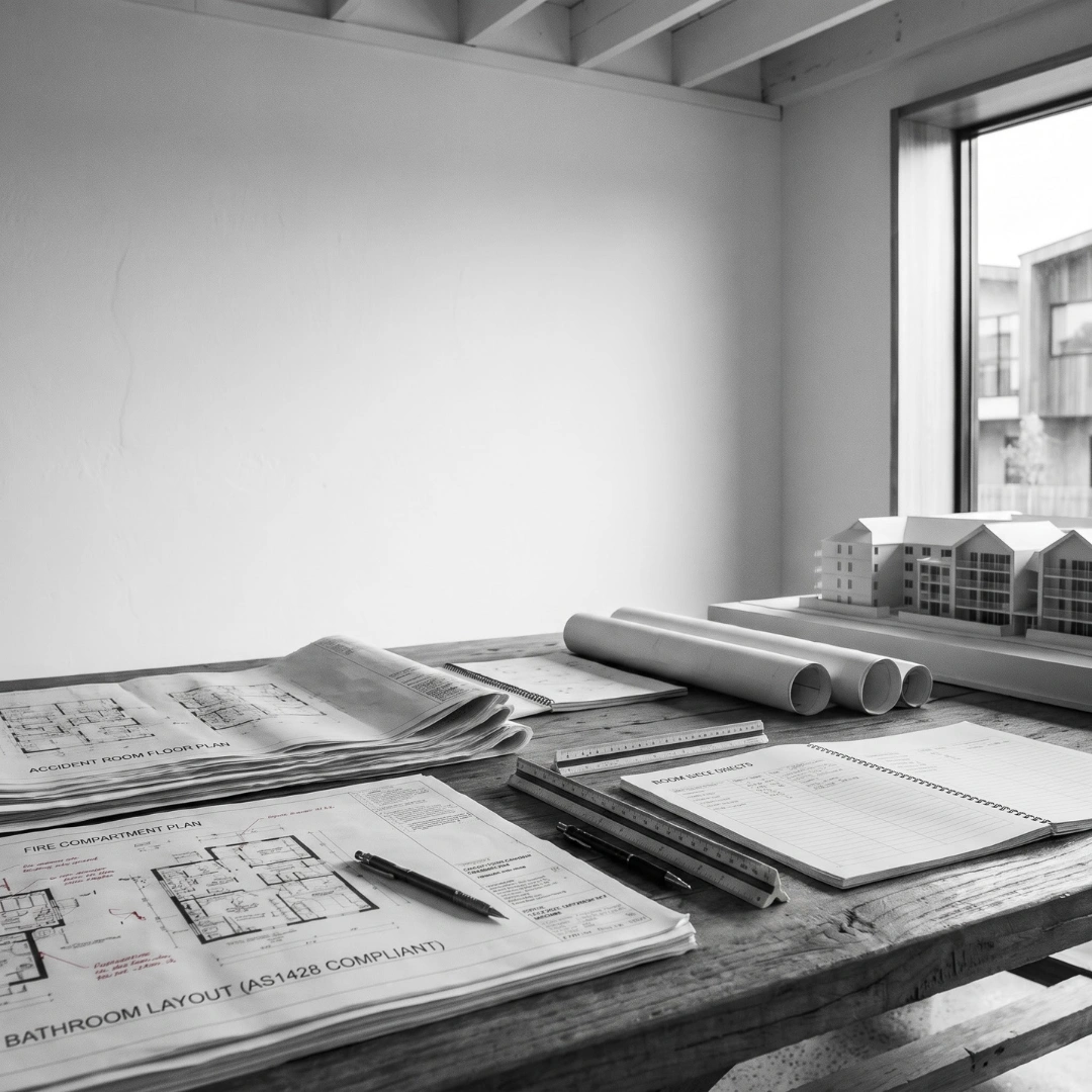
A drawing looking finished and a drawing being construction-ready aren't automatically the same thing. Construction-ready generally means a drawing, or a full set, satisfies several conditions at once: every dimension needed to build the element is shown or calculable, every material and finish is specified clearly enough to price and procure, every junction between different systems or materials is resolved rather than implied, the drawing complies with the applicable building code and planning approval conditions, and it's coordinated with every other drawing in the set, so a contractor never finds a wall in one position on a plan and a different position on a section.
A drawing can look highly detailed, full of hatching, labels, and clean linework, and still fail several of these conditions, particularly coordination with other disciplines, which is often invisible until someone actually checks the drawing against the structural or services model it needs to align with.
Working Drawings as a Contract Document
Once issued for construction, a working drawing set often becomes part of the legal contract between the client and the builder, not just a technical reference. That status changes how seriously ambiguity in the drawings needs to be taken. A note reading “confirm on site” or a dimension left approximate might be a minor inconvenience in a concept drawing; in a contract document, the same gap can become the basis of a variation claim or a dispute over what was actually agreed to be built. This is part of why working drawings carry a different level of rigor than the design drawings that precede them: they're not just describing a building, they're defining what the builder is contractually obligated to deliver.
Plans, Elevations, Sections, and Details: How the Set Builds Up
A working drawing set isn't one drawing type doing all the work. It's a layered combination, each type resolving a different aspect of the building at a different scale.
- Plans
- What it establishes: Spatial layout, room relationships, overall dimensions.
- Typical scale: 1:100 to 1:50.
- Elevations
- What it establishes: External appearance, material arrangement, openings.
- Typical scale: 1:100 to 1:50.
- Sections
- What it establishes: Vertical relationships, floor-to-floor heights, structural zones.
- Typical scale: 1:50 to 1:20.
- Details
- What it establishes: Exact construction at specific junctions, materials, fixings.
- Typical scale: 1:20 to 1:1.
Each drawing type references the others. A detail is meaningless without a section or plan calling it out and showing where it applies. This referencing structure is what makes a working drawing set a coordinated system rather than a stack of individually accurate but disconnected sheets, and it's also where a lot of documentation errors originate, when one drawing gets revised and the others referencing it don't get updated to match.
Dimensions, Annotations, and Specifications: The Information Layer
The drawn lines only carry part of a working drawing's information. Dimensions establish exact sizes, positions, and tolerances, and missing or ambiguous dimensioning is one of the most common reasons a contractor has to stop and raise a Request for Information mid-construction. Annotations, notes, keynotes, and callouts, connect the drawing to written requirements without duplicating them in full on every sheet. Specifications themselves define quality, performance, and installation requirements that a drawing alone can't fully convey, particularly around things like acceptable tolerances, testing requirements, and warranty conditions.
A drawing with clean geometry but incomplete or inconsistent dimensioning and annotation is functionally similar to a concept drawing wearing construction-drawing clothing. It looks the part without doing the job.
Coordination Between Architecture, Structure, and MEP
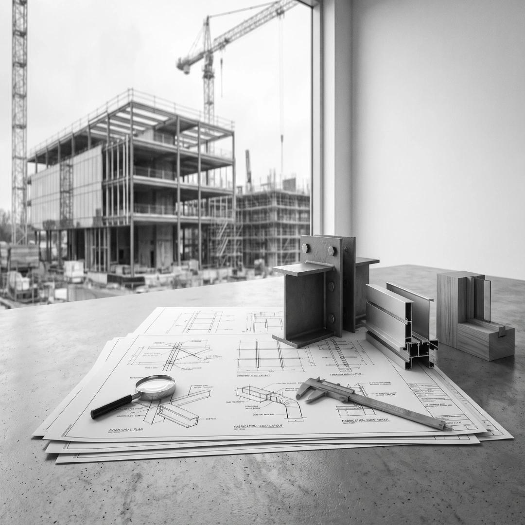
Working drawings rarely come from a single discipline working alone. Architectural drawings establish the spatial and material framework. Structural drawings, developed by an engineer, confirm the load-bearing elements, footings, columns, beams, slabs, that the architectural design depends on. Mechanical, electrical, and plumbing drawings route the building's services through the same spaces the architectural and structural drawings define.
Coordination between these three is where a construction-ready set earns that description or fails to. A ceiling height that works architecturally but doesn't account for the actual structural beam depth or the ductwork planned to run through the same void isn't resolved, it just hasn't been tested against the other disciplines yet.
BIM and Revit's Role in Producing Working Drawings
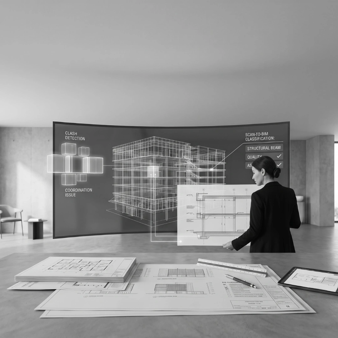
Building Information Modeling has changed how working drawings actually get produced, though it hasn't changed what they need to contain. Rather than drawing each plan, section, and elevation as a separate file, a Revit-based workflow generates those drawings as views of a single coordinated 3D model. A dimension or material change made once in the model updates every view referencing that element, which reduces the specific coordination failure described above, drawings disagreeing with each other because one was updated and the others weren't.
This doesn't make coordination automatic. A model can be geometrically consistent and still contain a genuine design conflict, a duct that fits in the model but was never actually checked against the structural beam occupying the same space in a federated review. BIM reduces the risk of drawings simply disagreeing with each other through manual inconsistency; it doesn't replace the judgment needed to resolve genuine conflicts between disciplines.
Common Documentation Mistakes When Moving From Concept to Working Drawings
Carrying forward concept-stage assumptions without re-testing them. A massing decision that worked at concept scale sometimes doesn't survive contact with actual structural spans or services requirements.
Incomplete dimensioning left as “to be confirmed.” A dimension deferred during design development sometimes never actually gets resolved before the set is issued.
Details that look finished but were copied without verification. A detail reused from a previous project can look completely resolved while not actually matching this project's specific conditions.
Drawings issued before structural and MEP coordination is actually complete. Pressure to meet a documentation deadline sometimes pushes a set out the door before every discipline has confirmed their systems fit together.
Inconsistent information between drawings and specifications. A material or dimension shown one way on a drawing and described differently in a specification creates genuine ambiguity about which document governs.
Drawing Review and Quality Control
A reliable review process checks more than whether a drawing set looks complete. It confirms that dimensions are consistent across every plan, section, and detail referencing the same element, that every detail called out on a plan or section actually exists and is correctly numbered, that structural and MEP drawings have been checked against the current architectural set rather than an earlier version, that specifications and drawings agree on materials and performance requirements, and that the set actually complies with the applicable building code and any specific planning approval conditions attached to the project.
Quality control works best as a scheduled, deliberate pass, not something caught incidentally while someone's working on an unrelated task. A dedicated review, ideally by someone who wasn't the primary author of the drawings being checked, catches the kind of internal inconsistency that's genuinely difficult for the person who produced the drawings to see in their own work.
Practical Best Practices for Producing Reliable Working Drawings
Treating the transition from concept to working drawings as a genuine re-testing of design decisions, not just an exercise in adding detail to an already-fixed design, catches problems while they're still cheap to resolve. Coordinating structural and MEP input early in construction documentation, rather than waiting until architectural drawings feel finished, avoids late-stage conflicts that force drawings to be reopened. Keeping dimensions, annotations, and specifications treated as one coordinated information system rather than three separately maintained documents reduces the inconsistency that creates ambiguity on site. And building in a dedicated, scheduled quality review before issue is what actually keeps a working drawing set reliable rather than merely detailed-looking.
Where This Fits Into Your Project
Understanding the real distance between a concept drawing and a genuinely construction-ready working drawing set is the difference between a documentation package that looks finished and one that actually holds up once a contractor starts pricing and building from it. The transition deserves the same rigor as the design work that precedes it, not less.
If your project's documentation needs a genuine coordination and quality-check pass moving from concept into working drawings, talk to us. We work across modelling and documentation, BIM coordination, and Revit drafting for architects, engineers, and contractors who need their drawing sets to actually be construction-ready, not just detailed-looking.
📧 Discuss Your Project: team@obelisk.au
11. FAQ Section
What are working drawings?
Working drawings are the detailed, dimensioned, technically complete set of architectural and engineering drawings a contractor uses to build a project, secure permits, and price the work, as distinct from earlier concept drawings that primarily communicate design intent.
What is the difference between concept drawings and working drawings?
Concept drawings communicate design intent, spatial arrangement, form, and material direction, early in a project and are tested against client feedback. Working drawings are the fully dimensioned, technically resolved documents produced later that a contractor can actually build from.
Are working drawings the same as construction drawings?
The terms are widely used interchangeably in current practice. Historically, working drawings referred specifically to the architectural graphic portion of the documentation, while construction documents is the broader term, but in everyday use most professionals treat the terms as describing the same construction-ready package.
What makes a drawing construction-ready?
A construction-ready drawing has complete, accurate dimensions, clearly specified materials and finishes, resolved junctions between systems, compliance with the applicable building code and approval conditions, and coordination with every other drawing in the set.
What information do working drawings typically include?
A working drawing set typically includes fully dimensioned plans, elevations, sections, and details, along with annotations, keynotes, and specification references covering materials, structural information, and MEP systems.
Who prepares working drawings?
Working drawings are typically prepared collaboratively by the architect and the engineers of record, structural, mechanical, electrical, and plumbing, each producing and coordinating their own discipline-specific drawings within the same set.
Why do working drawings need to be coordinated between architecture, structure, and MEP?
Because all three disciplines occupy and rely on the same physical space in the finished building. An architectural ceiling height, a structural beam depth, and MEP ductwork all have to be resolved together.
Can a contractor build directly from concept drawings?
No. Concept drawings are deliberately not fully dimensioned or technically resolved, and building from one would require the contractor to make decisions that should be resolved by the design team first.
How does BIM change the way working drawings are produced?
BIM lets working drawings generate as views of a single coordinated 3D model rather than as separately maintained files, so a change made once updates every view referencing that element, though it doesn't replace the active coordination process needed to catch genuine conflicts.
What is the most common mistake when transitioning from concept to working drawings?
Carrying forward concept-stage assumptions, a massing decision, an approximate dimension, without re-testing them against actual structural, services, and code requirements.
Do working drawings need to comply with building codes?
Yes. Working drawings need to demonstrate compliance with the applicable building code and any specific conditions attached to a project's planning approval, since permitting authorities review the working drawing set specifically for this.
How detailed should a working drawing be compared to a concept drawing?
Significantly more detailed. Where a concept drawing might show an approximate wall location and general material direction, a working drawing shows the wall's exact thickness, structural makeup, fire rating if applicable, and how it meets every adjacent element.
TABLE OF CONTENTS





















.png)
.png)
.webp)