

Revit Modeling Explained: From Concept Sketch to Coordinated Model
%20(1).png)
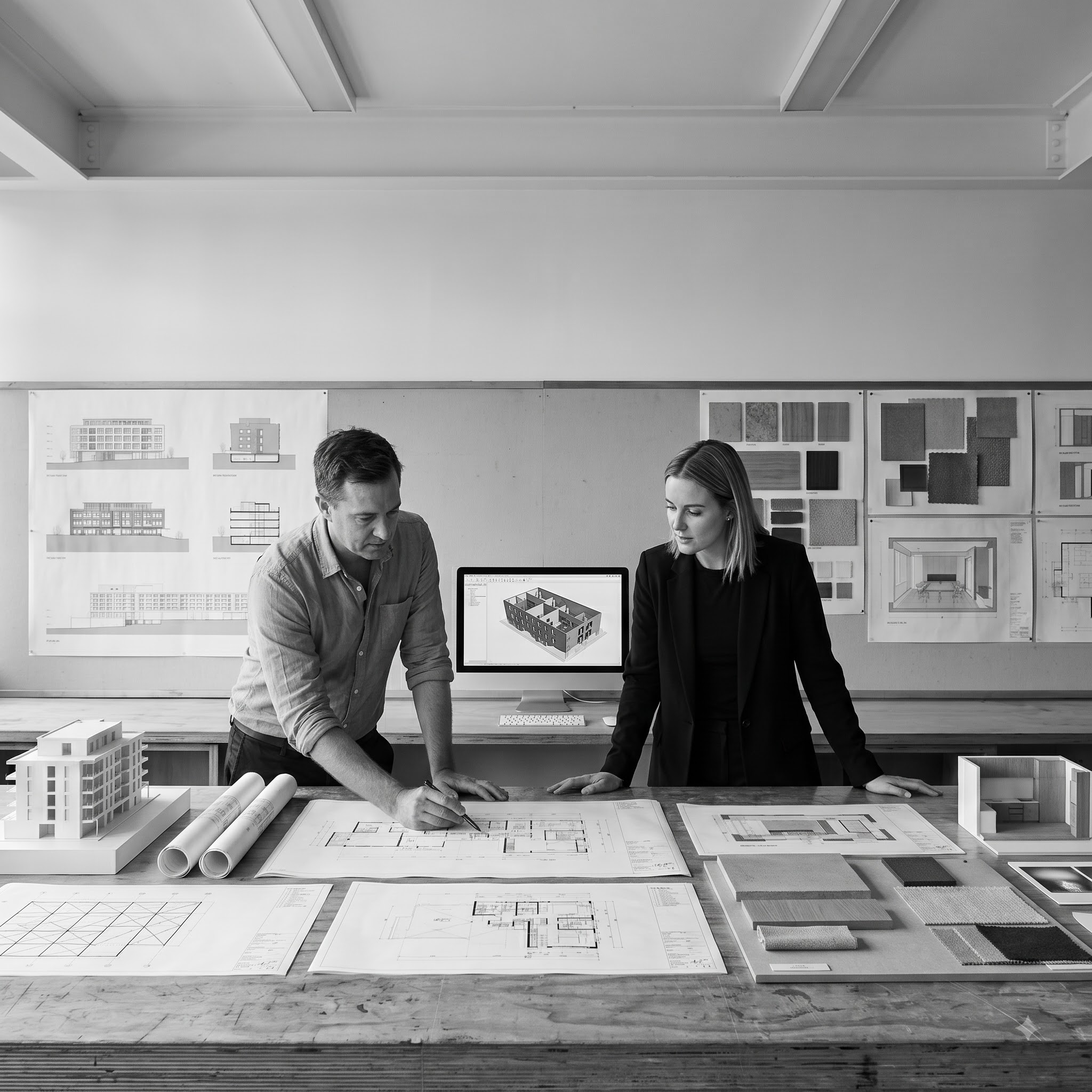
A concept sketch and a coordinated BIM model look nothing alike, and the distance between them is where most of the actual work happens. Revit modeling is the process that closes that gap: turning a rough massing idea into a structured, data-rich model that architects, structural engineers, and MEP engineers can all work inside, check against each other, and eventually build from.
This isn't a "what is Revit" explainer. It's a walk through how a Revit model actually develops, what happens at each stage, where the different disciplines meet, and where projects commonly go wrong along the way.
What Revit Modeling Actually Means
Revit modeling is the process of building a structured, information-rich digital model of a building inside Autodesk Revit, where every wall, duct, beam, and door isn't just a shape but an object carrying data: material, dimensions, fire rating, cost code, manufacturer information, and its relationship to every other element around it. The model isn't a static 3D file. It's a database with a visual representation attached, and that distinction is the whole point of Revit modeling as a discipline rather than just a drawing exercise.
A finished Revit model for a mid-size commercial project might contain architectural, structural, and MEP elements from three or more separate teams, linked together through a shared coordinate system, checked for physical clashes, and structured well enough that a schedule, a quantity takeoff, or a construction drawing can be generated directly from it rather than drawn separately.
How Revit Modeling Differs From Simple 3D Modeling
A 3D model built in a general-purpose visualization tool shows geometry. It looks like a building. Revit modeling produces something functionally different: parametric, data-carrying objects that understand their own relationships to the rest of the model. Move a wall in a properly built Revit model and the floor plan, sections, elevations, and any schedule referencing that wall update automatically. Move the equivalent surface in a pure visualization model and nothing else changes, because there was never a relationship to update.
This matters practically, not just conceptually. A firm producing renderings only needs geometry and materials to look right from a camera angle. A firm producing a model that will drive construction documentation, quantity takeoffs, and multidisciplinary coordination needs every element correctly categorized, parameterized, and related to the elements around it.
From Concept Sketch to Model: How the Workflow Actually Starts
Setting Up the Project: Levels, Grids, and Shared Coordinates
Before any wall gets modeled, a Revit project needs its levels (the floor-to-floor datum planes the whole building references) and grids (the structural reference lines columns and walls align to) established correctly. Get a level height wrong at this stage and every element modeled against it inherits the error. Shared coordinates matter just as much: when architectural, structural, and MEP models are being developed by separate teams and eventually linked together, they need to agree on a single coordinate system and true north orientation from the outset.
Choosing a Template and Establishing Standards
A Revit template preloads the project with the family types, view templates, naming conventions, and parameter setups a firm has standardized on. Starting from a well-maintained, firm-standard template rather than a blank file saves substantial rework later. On multidisciplinary projects, agreeing on these standards and documenting them in a BIM Execution Plan before modeling starts is what stops three teams from independently inventing three different naming conventions for the same kind of element.
Architectural Modeling in Revit
Architectural modeling establishes the building's envelope, internal layout, and the elements everyone else will need to coordinate around: walls, floors, roofs, doors, windows, stairs, and the vertical circulation and egress paths that shape the whole plan. This is typically where the concept sketch first becomes a Revit model, translated first as rough massing and then refined into actual building elements as the design solidifies through schematic design and design development.
The architectural model usually establishes the project's coordinate system and levels for everyone else, which makes early accuracy here disproportionately important. A shifted grid or an incorrect level height discovered after structural and MEP teams have already built against it is a coordination problem that costs real time to unwind.
Where Structural Modeling Fits Into the Workflow
Structural modeling develops the building's load-bearing skeleton, footings, columns, beams, slabs, and bracing, often working from the architectural model as a linked reference so the structural grid aligns with the architectural one from the start. Structural engineers frequently link their Revit model to analysis software to verify load paths and member sizing, then bring resolved structural elements back into the coordination model.
The practical friction point between architecture and structure shows up in things like beam depth: an architect wants a certain ceiling height, a structural engineer needs a beam of a certain depth to span a given distance, and the two requirements have to be resolved together rather than architecture assuming a beam will simply fit into whatever space is left over.
Where MEP Modeling Fits Into the Workflow
Mechanical, electrical, and plumbing modeling routes ductwork, piping, cable trays, and equipment through the building, and this is consistently where the highest volume of physical clashes originates, because MEP systems, structural elements, and architectural ceiling heights are all competing for the same limited ceiling void. MEP modelers typically link both the architectural and structural models as references, since duct and pipe routing depends on knowing exactly where beams, ceilings, and walls actually sit.
MEP models also tend to be the most information-dense in a coordinated model: flow rates, electrical loads, pipe sizing, and equipment schedules are all embedded directly in the modeled elements, which is what allows mechanical and electrical schedules to be generated from the model rather than compiled separately.
Families and Parameters: What Actually Makes a Model "BIM"
A Revit family is a reusable, parametric definition of a building component, a specific door type, a light fixture, or a structural column that can be placed repeatedly through a project while carrying consistent data and behavior. Parameters are the data fields attached to those families and to model elements generally: dimensions, materials, fire ratings, cost codes, manufacturer part numbers, and anything else a project needs to track.
This is the mechanism that separates a Revit model from a 3D visualization. A door family with the correct fire rating parameter populated lets a fire-rated door schedule generate automatically. A model built without disciplined parameter use might look complete and still be functionally hollow: geometry with no usable data behind it.
Views, Worksets, and Phasing: How Teams Actually Work Inside One Model
A Revit model isn't edited through one single screen. Views, plans, sections, elevations, 3D views, and schedules are all different windows into the same underlying model, controlled by view templates that set consistent graphics, visibility, and detail levels across a project. A firm with disciplined view template standards produces a documentation set that looks consistent sheet to sheet.
Worksets let multiple people work inside the same central model simultaneously, each checking out the elements they're actively editing without locking everyone else out of the file. Phasing lets a model represent different points in time, existing conditions, demolition, and new construction within the same file rather than as separate models, which matters most on renovation and adaptive reuse projects.
Level of Development (LOD) and How It Shapes a Revit Model
Level of Development describes how much detail and reliability a modeled element carries at a given project stage, and it's one of the most misunderstood concepts in Revit modeling because it's frequently confused with Level of Detail, a similar-sounding but distinct idea about visual complexity rather than information reliability.
At LOD 100, an element represents conceptual massing, an approximate size, shape, and location, and this is typical of concept design. LOD 200 moves to generalized systems with approximate quantities, size, shape, and location, matching the schematic design stage. LOD 300 represents precise geometry, with accurate size, shape, location, and orientation, and it's typical of design development and construction documentation. LOD 350 carries everything in LOD 300 plus the interfaces with other building systems needed for coordination, which is why it's the level most associated with trade coordination. LOD 400 reaches fabrication-level detail, ready for manufacturing and assembly, and applies to shop drawings and fabrication. LOD 500 represents a verified as-built condition, used at project closeout and for facility management.
Agreeing LOD targets for each discipline at each project stage and documenting them in the BIM Execution Plan avoids the common failure mode where one discipline models to LOD 300 while another is still working at LOD 200, making any coordination review between them close to meaningless.
Multidisciplinary Coordination: Linking Models Together
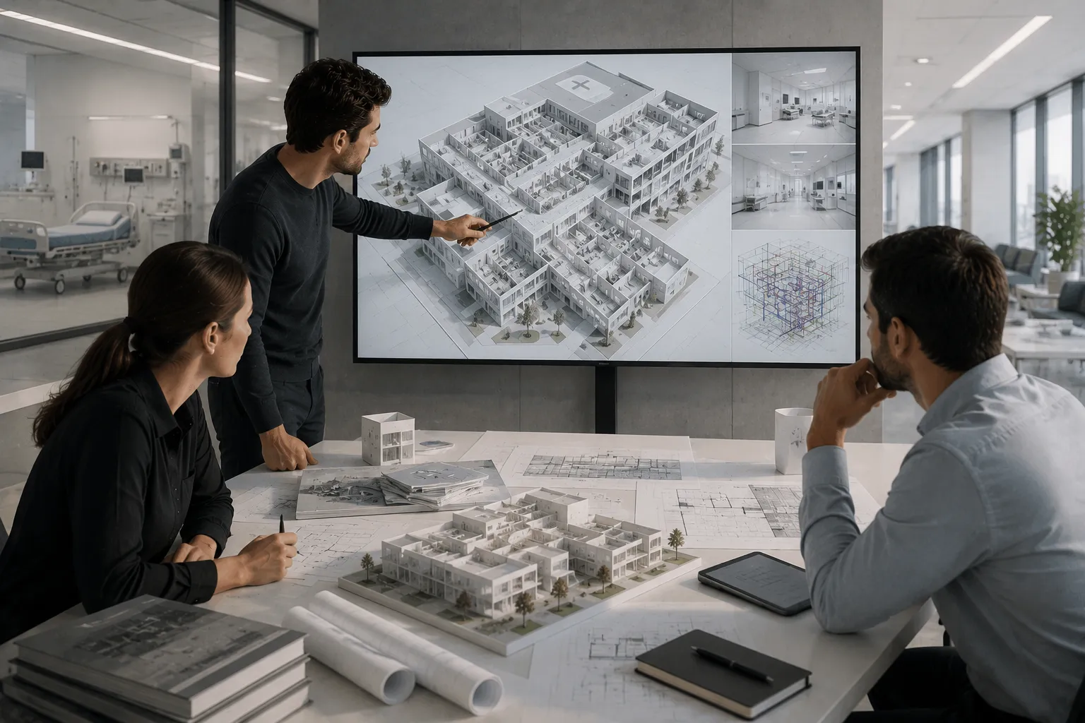
Coordination happens through linking, not merging. Each discipline maintains its own Revit model, and those models get referenced into each other or into a shared coordination environment as linked files that update automatically as the source model changes. An architect working in Revit can link the structural and MEP models as read-only reference geometry, seeing exactly where a column or a duct sits without that geometry becoming part of the architectural model itself.
This is why shared coordinates matter so much earlier in the process. A model linked in with the wrong coordinate system or true north setting will appear rotated or offset relative to everything else, and catching that early is far cheaper than discovering it once federated coordination review is already underway.
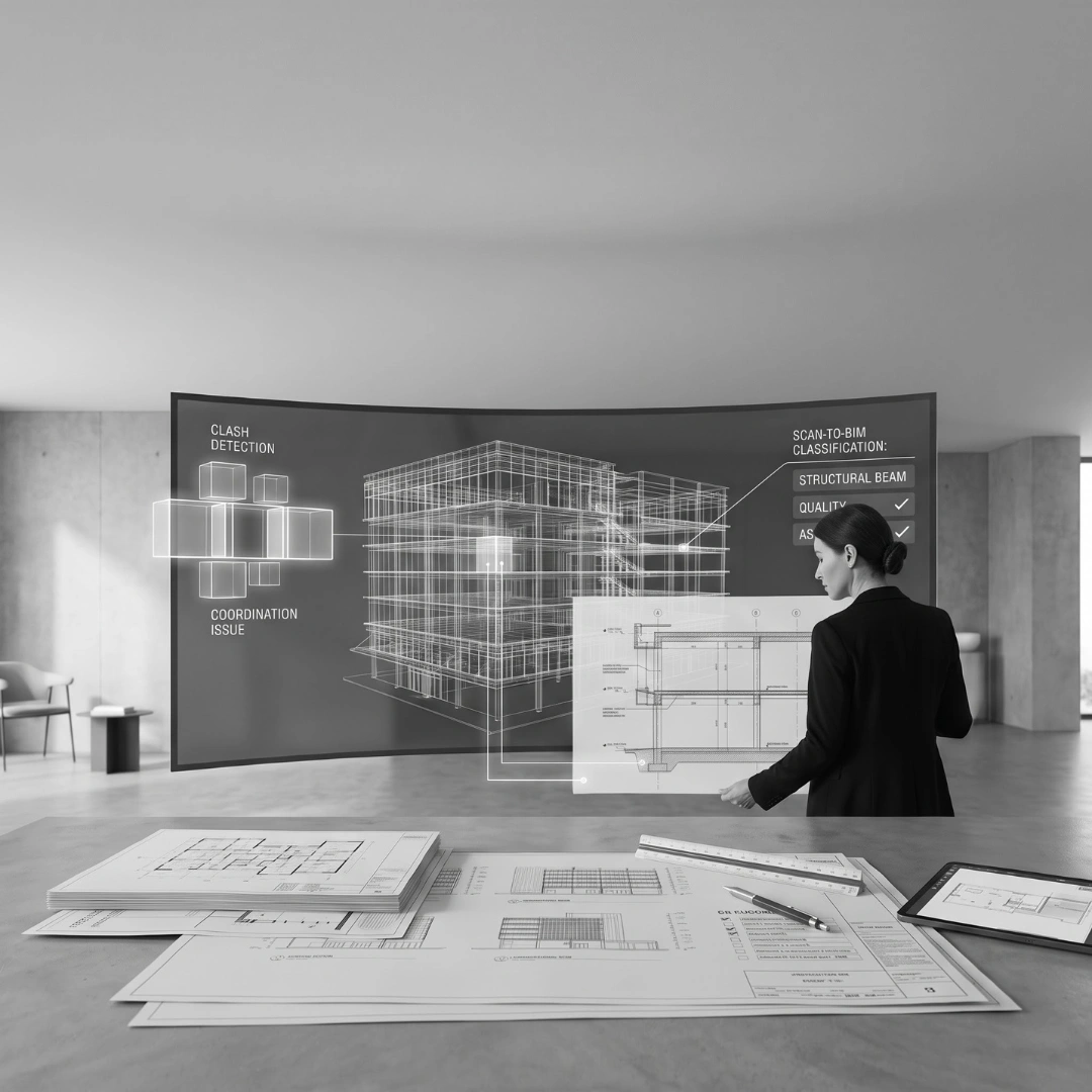
Clash Detection: Turning Separate Models Into One Coordinated Model
Clash detection is the process of running the combined, federated models against each other, usually in a platform like Navisworks, to identify physical conflicts: a duct running through a structural beam, a sprinkler head landing inside a light fixture, or a door swing that collides with equipment. On a well-run project, this happens on a recurring cycle through design development and documentation, not as a single check right before construction.
A raw clash report on a complex project can easily contain thousands of individual clashes, many of them duplicates or the same conflict repeated across a run of identical elements. Effective coordination workflows group, triage, and assign ownership of clashes rather than treating the raw report as an action list, and each clash needs to be tracked to actual resolution in the model, not just marked as reviewed.
Revit Modeling vs. Traditional 3D Modeling vs. CAD
2D CAD produces lines representing geometry, with no relationships between elements since every view is drawn independently. It doesn't support schedules or takeoffs, which require manual measurement, and coordination across disciplines happens through manually overlaying separate drawings. It is suited for construction documentation, but that documentation has to be maintained manually.
Simple 3D modeling produces visual geometry, often intended for renders, with only limited, mostly visual relationships between elements. It doesn't support schedules or takeoffs and isn't typically used for cross-disciplinary coordination. It's rarely suited for construction documentation, since the geometry often isn't build-accurate.
Revit modeling, as BIM, produces data-rich parametric building elements with full relationships between elements, so changes propagate automatically across views and schedules. It supports schedules and takeoffs directly, generated from model data, and supports coordination across disciplines through federated linking with clash detection. It's well suited for construction documentation, since drawings generate directly as views of the model.
From Coordinated Model to Construction Documentation
Once a model reaches an appropriate LOD and has been through coordination and clash resolution, construction documentation, plans, sections, elevations, and details, gets generated as views of that same model rather than drawn as separate files. This is one of Revit modeling's clearest practical payoffs: a dimension change made once in the model updates every drawing referencing that element, instead of requiring someone to manually update a floor plan, a section, and a schedule separately.
Quantity takeoffs and cost estimating draw from the same source. Because model elements carry real dimensions and material data, quantities can be scheduled directly rather than measured off drawings, and a design change flows through to an updated quantity automatically.
Common Revit Modeling Mistakes
Modeling geometry without populating parameters. A model that looks complete but has empty or generic parameter fields cannot support schedules, quantity takeoffs, or code compliance checks that depend on that data being there.
Ignoring shared coordinates until coordination is already underway. Setting up coordinates properly at project start takes minutes. Fixing a misaligned linked model after weeks of separate discipline modeling is a real, avoidable cost.
Modeling to inconsistent LOD across disciplines. One team modeling in fabrication-level detail while another is still at a conceptual stage makes any joint coordination review unreliable.
Treating clash detection as a single pre-construction event. Running one clash check right before documentation is issued catches problems too late to resolve cheaply.
Skipping a BIM Execution Plan on multidisciplinary projects. Without an agreed plan covering coordinates, naming conventions, and LOD targets, every team defaults to its own internal habits.
Best Practices for Professional Revit Modeling
Establish levels, grids, and shared coordinates correctly before any discipline begins detailed modeling. Start from a maintained, firm-standard template rather than a blank project file. Agree LOD targets per discipline per project stage in a documented BIM Execution Plan. Populate parameters as elements are modeled, not as an afterthought once documentation is due. Link, don't merge, discipline models, and keep shared coordinates consistent across every linked file. Run clash detection on a recurring cycle, with clashes assigned an owner and tracked to resolution. Validate the model against its intended LOD before treating it as coordination-ready.
Frequently Asked Questions
What is Revit modeling used for?
Revit modeling is used to build a data-rich, coordinated digital model of a building that supports design development, multidisciplinary coordination, construction documentation, quantity takeoffs, and, where properly maintained, facility management after handover.
How is Revit modeling different from BIM in general?
BIM is the broader process and philosophy of managing structured building information across a project's lifecycle. Revit modeling is the practical, software-specific act of building that information-rich model inside Autodesk Revit specifically.
What is the difference between architectural, structural, and MEP Revit modeling?
Architectural modeling covers the building envelope, layout, and circulation. Structural modeling covers the load-bearing skeleton, footings, columns, beams, and slabs. MEP modeling covers mechanical, electrical, and plumbing systems, each typically maintained as its own linked model.
What does LOD mean in Revit modeling?
Level of Development describes how much detail and reliability a modeled element carries at a given stage, ranging from LOD 100 (conceptual massing) to LOD 500 (verified as-built).
Why do Revit models need to be linked rather than combined into one file?
Linking lets each discipline maintain control over its own model while referencing the others for coordination, and it keeps file sizes and permissions manageable across separate firms.
What is clash detection in Revit modeling?
Clash detection is the process of checking linked or federated models against each other, typically in a platform like Navisworks, to identify physical conflicts between elements from different disciplines before construction begins.
What are Revit families, and why do they matter?
Families are reusable, parametric definitions of building components that carry consistent geometry and data wherever placed. They're central to keeping a model both efficient to build and reliably data-rich.
Can Revit models be used for quantity takeoffs?
Yes. Because Revit elements carry real dimensional and material data, quantities can be scheduled directly from the model rather than measured manually from drawings.
What is a BIM Execution Plan, and why does it matter for Revit modeling?
A document agreed at project start covering shared coordinates, software platforms, LOD targets by stage, and model ownership, keeping multiple teams modeling to compatible standards.
How do shared coordinates affect multidisciplinary Revit modeling?
Shared coordinates ensure architectural, structural, and MEP models align correctly in 3D space when linked together. Getting this wrong means linked models appear offset or rotated.
Is Revit modeling only useful for large or complex projects?
No, though coordination benefits scale with project complexity. Smaller projects still benefit from Revit modeling's documentation efficiency and quantity accuracy.
How does Revit modeling support construction documentation?
Construction drawings generate as views of the coordinated model rather than being drawn separately, so a change made once updates consistently across every drawing that references it.
Where This Fits Into Your Project
Understanding the journey from a concept sketch to a coordinated Revit model is one thing. Actually running that process cleanly across architecture, structure, and MEP, with the coordinates, LOD targets, and clash detection cadence that make coordination genuinely reliable, is where the real value gets won or lost.
If you're scoping Revit modeling for an upcoming project, or your current model isn't delivering the coordination and documentation benefit it should, talk to us. We work across modelling and documentation, BIM coordination, and Revit drafting for architects, engineers, and contractors who need the model to actually hold up through design, coordination, and construction.
📧 Discuss Your Project: team@obelisk.au
TABLE OF CONTENTS


















.png)
.png)
.webp)