


Scan-to-BIM for Existing Buildings: Complete As-Built Documentation Guide 2026

A heritage building renovation requires accurate existing conditions documentation. Traditional measured survey approaches send multiple technicians on-site for days measuring room dimensions, ceiling heights, window locations, structural elements, and building services with tape measures, laser distance meters, and total stations. The resulting documentation shows what was measured but inevitably misses hidden conditions, complex geometries, services above ceilings, and three-dimensional relationships. Contractors encounter undocumented conditions weekly generating RFIs, variations, and schedule delays.
Scan-to-BIM workflow captures the same building in hours rather than days using 3D laser scanning technology recording millions of measurement points creating comprehensive digital record of existing conditions. The resulting point cloud dataset documents everything visible from scan positions including complex curved surfaces, ornate heritage details, service penetrations, and spatial relationships impossible to capture efficiently through traditional measurement. Converting point cloud data to intelligent BIM model delivers as-built documentation supporting design, coordination, construction, and facilities management with accuracy and completeness unachievable through conventional approaches.
This comprehensive guide provides BIM Managers and digital practice leaders with complete scan-to-BIM workflow for existing building documentation. You'll learn when scan-to-BIM delivers value versus traditional approaches, 3D laser scanning technology options and selection criteria, scan planning and field data capture methodology, point cloud processing and registration techniques, modeling from point cloud workflows in Revit and other platforms, accuracy standards and quality control requirements, deliverable formats and documentation options, equipment investment versus outsourcing decision frameworks, and advanced applications including reality capture for progress monitoring and clash detection.
When Scan-to-BIM Delivers Value
Scan-to-BIM represents significant investment in equipment, software, training, or outsourced services. Understanding applications where technology delivers clear value versus projects suited to traditional approaches guides appropriate deployment.
High-Value Scan-to-BIM Applications
Heritage and conservation projects where existing building fabric documentation requires precision, ornate details resist simple measurement, and historical record preservation has value beyond immediate project benefit strongly from scan-to-BIM. Point cloud captures intricate plasterwork, decorative elements, and architectural features with geometric fidelity impossible through manual measurement while creating permanent digital archive.
Complex existing buildings including industrial facilities with extensive services, multi-level structures with complex vertical relationships, and buildings with irregular or curved geometries benefit from comprehensive three-dimensional capture. Traditional measurement struggles with spatial complexity that point cloud naturally records.
Large-scale retrofits and adaptive reuse projects requiring existing conditions understanding across substantial building areas achieve efficiency through scanning. Scanning 10,000+ square meter existing building in 2-3 days compares favorably to weeks of traditional measurement while delivering more complete documentation.
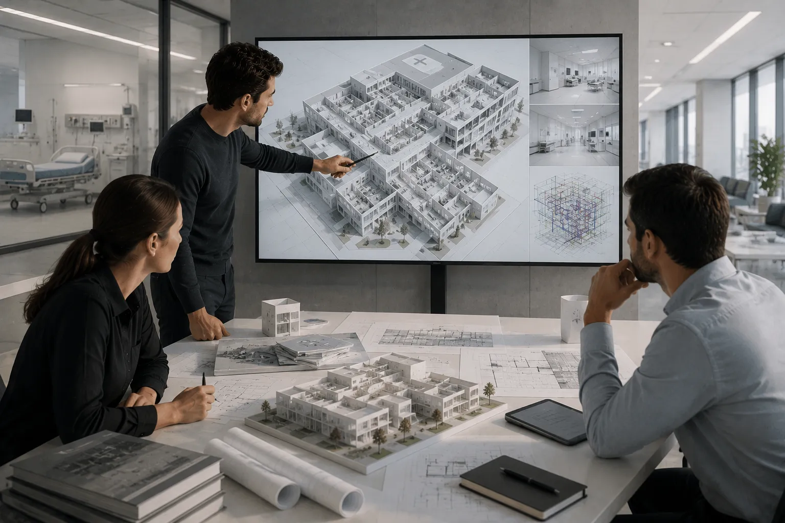
Occupied buildings where measurement disruption creates operational impact benefit from scanning's speed. Hospital renovations, operating retail facilities, or occupied offices minimize disruption through rapid scan capture versus extended measurement access.
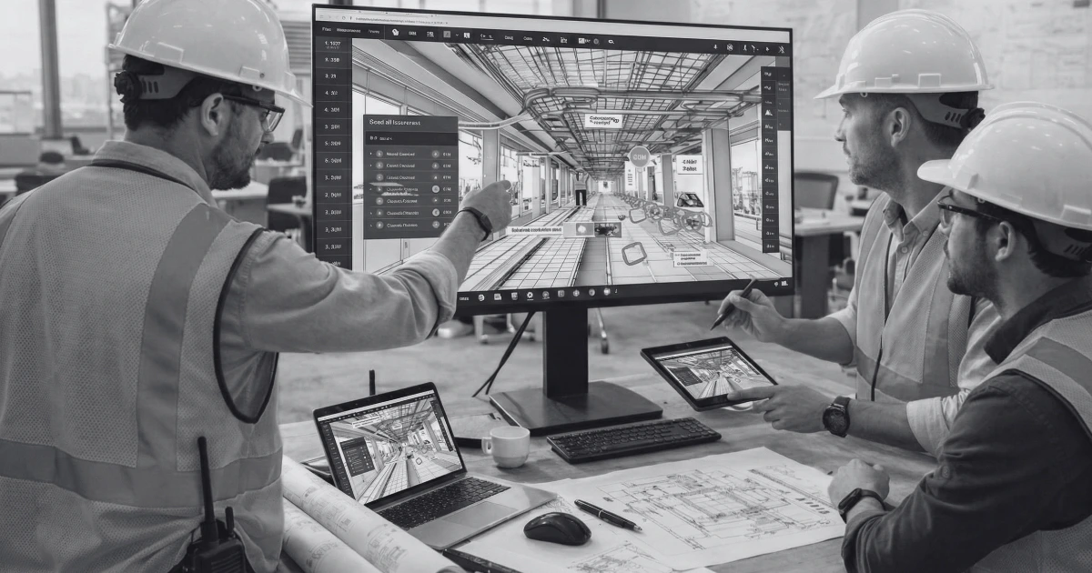
Coordination-critical projects where new design must integrate precisely with existing structure and services use point cloud overlay in BIM coordination models. Scanning existing conditions enables clash detection between new design and actual as-built conditions preventing expensive site conflicts.
Projects Suited to Traditional Measurement
Simple rectangular buildings with straightforward geometry, minimal services complexity, and standard construction may not justify scanning investment. Traditional measurement of 200-square-meter warehouse with simple portal frame structure proves faster and more cost-effective than mobilizing scanning equipment.
Small-scale renovations affecting single rooms or limited building areas often complete traditional measurement more efficiently. Scanning entire building to renovate single bathroom adds unnecessary scope and cost.
Projects with adequate existing documentation where minor verification suffices may not require comprehensive scanning. Updating 5-year-old as-built drawings for minor modifications works efficiently through selective traditional measurement.
Budget-constrained projects where scanning cost represents substantial portion of total design fee may prove uneconomical. Small residential additions or minor commercial renovations operate within fee structures challenging to accommodate scanning investment.
3D Laser Scanning Technology Options
2026 scanning technology landscape includes diverse options with varying capabilities, accuracy, speed, and cost profiles.
Terrestrial Laser Scanners (TLS)
Terrestrial laser scanners represent traditional scan-to-BIM workhorses providing highest accuracy and longest range. Leading 2026 TLS platforms include Faro Focus Premium (±1mm accuracy at 10m, 2 million points per second, 350m range), Leica RTC360 (±1mm accuracy, 2 million points per second, integrated HDR imaging), Trimble X12 (±2mm accuracy, 3D registration capabilities, rugged design), and emerging hybrid systems combining scanning with photogrammetry.
TLS advantages include sub-centimeter accuracy suitable for precision applications, long range enabling large space capture from minimal positions, established workflows and extensive software ecosystem, and comprehensive point cloud density. TLS limitations include stationary setup requiring tripod placement at each scan position, registration requiring targets or cloud-to-cloud alignment, 10-30 minutes per scan position including setup and capture, and higher equipment cost ($25,000-$80,000 AUD for professional systems).
Typical TLS deployment scans existing buildings from 20-100+ positions depending on complexity and required coverage, achieving overall accuracy ±5-10mm after registration, and delivering comprehensive point cloud suitable for architectural BIM modeling.
Mobile Mapping Systems (MMS)
Mobile mapping combines continuous scanning with SLAM (Simultaneous Localization and Mapping) algorithms enabling walking-path data capture. Leading 2026 MMS platforms include NavVis VLX (wearable backpack system, 30mm accuracy, rapid capture), GeoSLAM ZEB series (handheld and backpack options, 15-30mm accuracy), and emerging smartphone-based systems with improving capabilities.
MMS advantages include rapid capture (walking speed data collection, 3,000+ sqm per hour), simplified workflow without stationary scan positions, automatic registration through SLAM processing, and accessibility for operators with minimal training. MMS limitations include lower accuracy than TLS (typically ±15-30mm), reduced point density affecting fine detail capture, potential registration drift in large buildings or GPS-denied environments, and evolving software ecosystem still maturing.
MMS deployment suits rapid reconnaissance scanning, large building capture where TLS setup time becomes prohibitive, preliminary documentation where sub-centimeter accuracy unnecessary, and combination with TLS for comprehensive coverage (TLS for precision areas, MMS for general documentation).
Handheld Scanners
Handheld SLAM scanners provide highly portable scanning capability. 2026 platforms include Leica BLK2GO (handheld with visual SLAM, 8-10mm accuracy), Matterport Pro3 (structured light scanning, accessible entry point, 20mm accuracy for architectural purposes), and iPhone/iPad LiDAR (consumer technology, 10-30mm accuracy, appropriate for preliminary assessment).
Handheld advantages include extreme portability enabling access to confined spaces, minimal training requirement for basic capture, lower equipment cost ($4,000-$25,000), and rapid deployment without setup overhead. Limitations include variable accuracy dependent on operator technique and conditions, limited range requiring proximity to surfaces, point cloud density variations, and registration challenges in feature-poor environments.
Handheld scanner applications include confined space scanning (ceiling voids, plant rooms, inaccessible areas), preliminary documentation and feasibility assessment, supplementary capture filling TLS/MMS coverage gaps, and accessible entry point for firms exploring scan-to-BIM.
Photogrammetry and Hybrid Approaches
Photogrammetry creates 3D models from 2D photographs through structure-from-motion algorithms. 2026 photogrammetry software includes RealityCapture, Agisoft Metashape, and Autodesk ReCap Photo processing conventional photography or drone imagery into point clouds and textured meshes.
Photogrammetry advantages include equipment accessibility (digital cameras or drones), textured output providing visual context, and potential cost savings through conventional camera use. Limitations include processing complexity and time, accuracy variability (typically ±20-50mm architectural applications), difficulty with reflective or featureless surfaces, and requirement for controlled lighting and overlap.
Hybrid workflows combine technologies leveraging strengths: TLS for primary structure and precision elements, MMS for rapid general coverage, handheld for confined spaces, and photogrammetry for exterior facades or textured documentation.
Scan Planning and Field Data Capture
Successful scan-to-BIM projects begin with comprehensive planning ensuring complete coverage, appropriate accuracy, and efficient field operations.
Pre-Scan Site Assessment
Site assessment before mobilization identifies project scope (building areas requiring scanning, exterior inclusion, site context), access constraints (working hours, security requirements, permits), environmental conditions (lighting, weather for exterior scanning, operational hazards), existing documentation review (floor plans informing scan planning, identifying areas of particular interest), and special requirements (accuracy tolerances, coordination with occupied operations).
Assessment output includes scan plan showing approximate scan positions, equipment selection matching project requirements and constraints, crew sizing and timeline estimation, and coordination with client regarding access and logistics.
Scan Position Planning
Scan position planning ensures complete coverage without excessive data redundancy. Planning principles include coverage overlap (adjacent scans overlapping 20-30% ensuring continuous point cloud), position spacing (typically 5-15 meters for TLS depending on room complexity and required detail), line-of-sight considerations (placing positions ensuring critical features visible), vertical coverage (including multiple levels, ceilings, underfloor areas where accessible), and registration strategy (target placement or cloud-to-cloud registration requirements).
Complex buildings may require 50-200+ scan positions achieving comprehensive coverage. Over-scanning creates processing burden and extended field time. Under-scanning creates coverage gaps discovered only during modeling requiring field remobilization.
Field Data Capture Methodology
Field scanning workflow includes equipment setup and calibration verification, systematic progression through building following scan plan, registration target placement (if using target-based registration) at strategic positions visible across multiple scans, individual scan capture (typically 5-30 minutes per position depending on scanner and settings), metadata recording (scan position identification, notes regarding specific features or conditions), and quality verification (checking coverage adequacy before demobilizing).
Experienced scan crews capture 15-30 scan positions daily for TLS (building complexity dependent) or 5,000-10,000 square meters daily for MMS systems. Field time represents 20-30% of total scan-to-BIM project duration with registration, processing, and modeling consuming majority.
Environmental Conditions and Challenges
Scanning accuracy and quality affected by environmental factors including reflective surfaces (glass, polished metal creating noise or voids in point cloud), moving objects (people, equipment captured as artifacts requiring cleanup), extreme lighting (direct sunlight, complete darkness affecting HDR capture and registration), atmospheric conditions (rain, fog, extreme temperatures affecting measurement), and electromagnetic interference (some environments affecting SLAM systems).
Mitigation strategies include optimal timing (scanning outside occupied hours, avoiding adverse weather), surface treatment (temporary dulling spray for problematic reflective surfaces), multiple scans (capturing dynamic environments at different times), and technology selection (choosing scanner appropriate for conditions).
Point Cloud Processing and Registration
Raw scan data requires processing transforming individual scan positions into unified coordinate system and optimized dataset.
Point Cloud Registration
Registration aligns multiple scan positions into single coordinated point cloud. Registration approaches include target-based registration using artificial targets (spheres, checkerboards) visible in multiple scans and surveyed or auto-registered, cloud-to-cloud registration using software algorithms identifying common features between overlapping scans (ICP - iterative closest point algorithms), and hybrid approaches combining targets for initial alignment with cloud-to-cloud refinement.
Registration software includes scanner-manufacturer platforms (Faro Scene, Leica Cyclone, Trimble RealWorks), third-party registration tools (Autodesk ReCap Pro), and open-source options (CloudCompare for basic registration tasks).
Registration quality assessment evaluates registration error typically targeting ±5-10mm overall accuracy, coverage completeness ensuring all building areas represented, and coordinate system establishment (project coordinate system, local coordinates, or geospatial coordinates).
Point Cloud Optimization and Cleanup
Raw registered point cloud requires optimization for downstream modeling including noise filtering removing erroneous points from reflections or measurement errors, point decimation reducing point density where excessive while maintaining geometric fidelity, segmentation separating building from context (furniture, equipment, temporary elements), and classification organizing points by element type (walls, floors, ceilings, equipment) where software enables automated classification.
Optimization reduces file sizes from raw capture (often hundreds of gigabytes) to manageable datasets (typically 5-50GB for building projects) while retaining geometric information necessary for modeling.
Point Cloud Formats and Standards
Point cloud data exchanged in various formats including E57 (ASTM standard, widely supported, contains scan position metadata, color, and intensity), RCP/RCS (Autodesk ReCap formats, optimized for Revit and AutoCAD integration), LAS/LAZ (common in surveying and GIS, compressed LAZ reduces file sizes), PTS/XYZ (simple ASCII formats, large file sizes, basic compatibility), and proprietary formats (scanner-specific formats requiring native software).
Format selection balances compatibility requirements, file size considerations, and metadata preservation needs. E57 emerging as de facto standard for archival and exchange given broad software support and comprehensive data capture.
Modeling from Point Cloud Data
Converting point cloud to intelligent BIM model represents most labor-intensive scan-to-BIM phase requiring skilled modelers and appropriate workflows.
Level of Accuracy (LOA) Standards
USIBD (United States Institute of Building Documentation) Level of Accuracy specifications define achievable accuracy based on modeling approach and point cloud quality. LOA specifications include LOA 10 (±50mm, preliminary assessment and massing), LOA 20 (±15mm, schematic design and general layouts), LOA 30 (±5mm, design development and coordination), LOA 40 (±3mm, construction documentation of complex elements), and LOA 50 (±1mm, precision fabrication or conservation).
Most architectural scan-to-BIM projects target LOA 30 (±5mm) representing balance between accuracy, effort, and typical design coordination requirements. Heritage documentation or precision manufacturing retrofit may require LOA 40-50. Preliminary assessments operate at LOA 10-20.
Modeling Methodology and Workflow
Revit point cloud modeling workflow loads optimized point cloud as linked background in Revit project, models building elements (walls, floors, roofs, structural elements) referencing point cloud geometry, creates custom families for non-standard elements (heritage details, irregular features), documents deviations where as-built conditions vary from idealized BIM representation, and organizes model matching scan-to-BIM deliverable requirements.
Modeling decisions address ideal versus actual representation (representing walls as perfectly plumb versus documenting actual out-of-plumb conditions), geometric simplification (capturing essential geometry versus exact surface irregularities), parametric versus non-parametric elements (using standard Revit families where appropriate versus custom in-place families), and documentation of assumptions where point cloud coverage incomplete or ambiguous.
Manual versus Automated Feature Extraction
Point cloud to BIM conversion ranges from fully manual modeling (modeler creating each element referencing point cloud) through semi-automated workflows (automated wall detection with manual verification/correction) to emerging fully automated extraction (AI/ML algorithms extracting building elements from point cloud).
2026 state-of-the-art includes EdgeWise Plant (automated industrial piping extraction), ClearEdge3D Verity (semi-automated architectural element detection), Revit point cloud modeling tools (manual workflow with point cloud snapping), and emerging AI-based extraction (rapid development but requiring substantial manual verification/cleanup).
Modeling productivity averages 50-150 square meters modeled per day (complexity dependent) for manual workflow, potentially 200-400 square meters per day with effective semi-automated tools, though automation effectiveness varies substantially with building regularity and point cloud quality.
Quality Control During Modeling
Model accuracy verification compares BIM model back to point cloud identifying deviations exceeding tolerance. Verification approaches include visual inspection overlaying model on point cloud in multiple views, section cut comparisons verifying vertical relationships and ceiling heights, key dimension verification measuring critical dimensions in model and point cloud, and CloudCompare or similar software performing automated cloud-to-mesh deviation analysis generating color-coded deviation maps.
Deviation analysis typically shows 80-90% of model within specified tolerance (±5mm for LOA 30) with larger deviations at geometric irregularities, point cloud noise areas, or modeling simplifications.
Accuracy Standards and Quality Control
Delivering specified accuracy requires systematic approach spanning capture through modeling with verification at each stage.
Accuracy Budget and Error Sources
Total system accuracy combines errors from multiple sources including scanner instrument accuracy (±1-3mm for professional TLS), registration error (±3-5mm typical for well-registered multi-scan project), point cloud processing and optimization (±1-2mm from filtering and decimation), modeling error from interpreter decisions (±2-5mm), and cumulative error propagation.
Targeting overall ±5mm accuracy (LOA 30) requires scanner accuracy ±2mm, registration error ±3mm, and modeling discipline ±3mm with statistical understanding that errors don't simply add linearly.
Verification and Validation Methodology
Multi-stage verification approach includes field verification capturing check measurements during scanning for post-processing verification, registration quality assessment evaluating registration reports and manual inspection of scan overlap zones, point cloud validation spot-checking point cloud dimensions against field notes or known dimensions, model validation comparing model to point cloud through deviation analysis, and final deliverable verification independent review before client delivery.
Check measurements using conventional survey or tape measurement at strategic locations (typically 20-50 checks per project) verify point cloud dimensional accuracy against independent measurement.
Documentation of Accuracy Achievement
Accuracy documentation accompanying scan-to-BIM deliverable includes accuracy statement specifying achieved LOA and methodology, registration report showing registration errors per scan position and overall network accuracy, deviation analysis results showing model-to-point-cloud deviation statistics and maps, and limitations documentation identifying areas where coverage was incomplete or accuracy may be reduced.
Transparent accuracy documentation manages client expectations and provides context for design decisions based on as-built model.
Deliverable Formats and Documentation
Scan-to-BIM projects deliver varied outputs matching project requirements and downstream use.
As-Built BIM Model Deliverables
BIM model deliverables include Revit model (or other platform - ArchiCAD, Vectorworks) at specified LOD (typically LOD 300-400 for as-built documentation), coordinated disciplines where structural, MEP also modeled from point cloud, and IFC export for platform-neutral exchange.
Model organization follows BIM standards including view organization, phase configuration showing existing vs. proposed, and accurate metadata (areas, volumes, element properties).
Point Cloud Deliverables
Point cloud data delivered alongside or instead of BIM model includes registered point cloud in agreed format (typically E57 plus RCP for Revit users), scan position data preserving individual scan locations for future reference, HDR imagery captured during scanning, and metadata including coordinate system, accuracy documentation, and scan date.
Point cloud delivered as reference for design team coordination, client facility management records, and future projects requiring existing conditions reference.
2D Documentation from Point Cloud
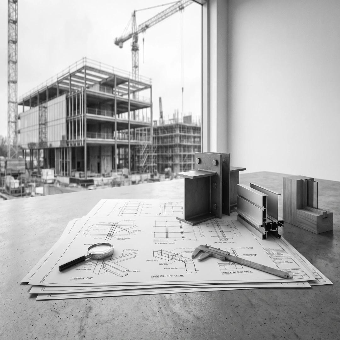
Traditional 2D deliverables extracted from point cloud include measured survey plans at specified scales showing existing conditions, elevations documenting building facades and significant interior elevations, building sections through critical areas, and reflected ceiling plans documenting existing services and ceiling conditions.
Hybrid workflows may deliver 2D documentation without full BIM model conversion where 3D model not required for project scope but scan-derived accuracy desired.
Specialized Deliverables
Project-specific deliverables include facade documentation for heritage or restoration, services mapping documenting existing MEP without full coordination model, topographic survey from terrestrial scanning, volume calculations for earthworks or material quantities, and progress monitoring comparing as-built against design at multiple construction phases.
Equipment Investment vs. Outsourcing Decision
Firms evaluating scan-to-BIM capability face build-versus-buy decision requiring careful analysis.
In-House Capability Investment
Building internal scan-to-BIM capability requires equipment acquisition (terrestrial scanner $25,000-$80,000, mobile mapping $40,000-$80,000, or handheld $4,000-$25,000), software licensing (registration software $2,000-$8,000 annually, modeling platform already owned, analysis tools $1,000-$3,000 annually), training investment (40-80 hours initial training, ongoing skill development), and staff allocation (dedicated or part-time scan technician, modelers with point cloud expertise).
Total first-year investment: $50,000-$120,000+ including equipment, software, training, and initial inefficiency learning curve.
Outsourced Service Costs
Outsourcing scan-to-BIM to specialized providers costs $2,000-$15,000+ per project depending on building size, complexity, accuracy requirements, modeling scope, and deliverable format.
Typical pricing: $0.15-$0.50 per square meter for scanning only, $0.50-$2.00 per square meter for scan-to-BIM including modeling (wide range reflecting complexity variation).
Break-Even Analysis
In-house capability breaks even when project volume justifies equipment investment. Simple analysis: $80,000 total investment / $5,000 average outsource cost per project = 16 projects to break even. Firm completing 15-20 scan-to-BIM projects annually breaks even in 12-18 months. Firm completing 3-5 projects annually requires 3-5+ years break-even making outsourcing likely more economical.
Additional considerations include capability development and competitive differentiation value, equipment depreciation and technology obsolescence (scanners improving rapidly), opportunity cost of capital investment, and staff utilization across scanning and other work.
Hybrid Approach
Many firms adopt hybrid strategy outsourcing field scanning while performing in-house point cloud processing and modeling, collaborating with scan providers on joint projects building internal expertise, investing in entry-level equipment (Matterport, handheld SLAM) for preliminary work while outsourcing precision scanning, or building capability selectively for specific practice areas (heritage, industrial) while outsourcing others.
Hybrid approach manages capital investment while developing expertise and serving client needs.
Advanced Applications and Emerging Technology
Scan-to-BIM technology evolving rapidly with expanding applications beyond traditional as-built documentation.
Construction Progress Monitoring
Regular scanning during construction tracks progress against schedule and design comparing as-built against design model at multiple phases, verifying dimensional accuracy during construction, documenting pre-cover conditions (structure, services before concealment), and supporting payment claims with verified progress.
Automated progress monitoring software analyzes point cloud scans identifying completed elements, comparing against schedule, and generating progress reports with increasing automation.
Quality Assurance and Clash Detection
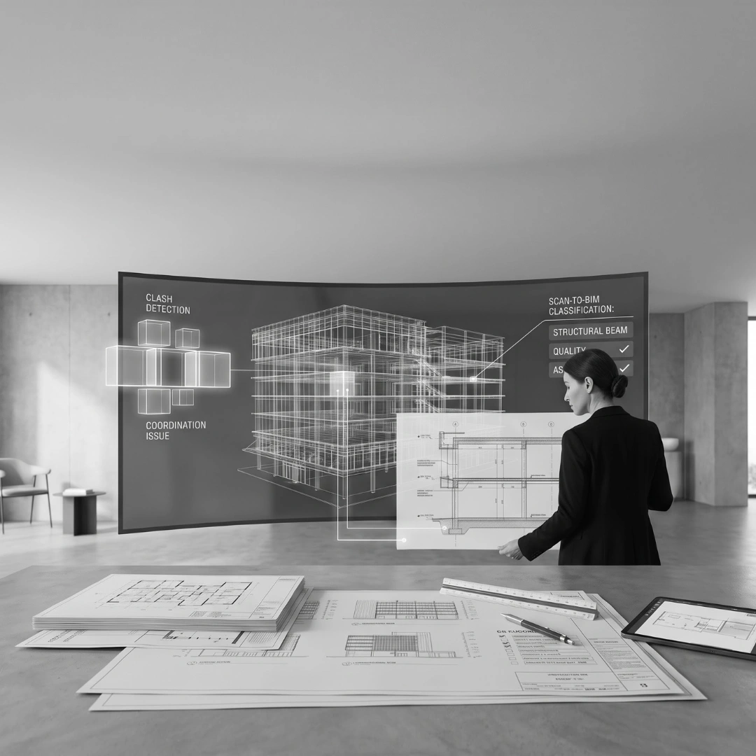
Point cloud overlay in BIM coordination models enables physical-to-digital clash detection verifying new design elements fit within actual existing conditions (not just documented existing conditions potentially inaccurate), identifying existing condition interferences before construction, and validating as-built installation compliance with design.
MEP coordination especially benefits scanning existing buildings capturing precise ceiling void conditions, structural elements, and existing services enabling clash-free new design integration.
Facility Management and Digital Twins
As-built scan-to-BIM models integrated into facility management systems creating spatial framework for asset management, maintenance planning and scheduling, space management and utilization analysis, and emergency response planning.
Digital twin integration connects real-time building data (sensors, BMS) with spatial geometry from scan-to-BIM documentation enabling operational optimization.
AI and Machine Learning Automation
Emerging AI/ML applications automate point cloud to BIM conversion through automated element detection and classification, damage and defect detection in heritage or maintenance applications, semantic segmentation organizing point cloud by building element, and predictive modeling inferring occluded conditions from visible geometry.
2026 automation improving rapidly but still requiring substantial human verification and refinement. Expect increasing automation capability through 2020s.
Mobile and Consumer Technology
iPhone/iPad LiDAR and emerging smartphone scanning capabilities democratize access to basic scanning technology. While accuracy (±10-30mm) insufficient for precision applications, smartphone scanning suits preliminary documentation, client communication and visualization, basic space planning, and accessible scanning introducing clients to technology value.
Consumer technology improving rapidly with potential to shift scan-to-BIM accessibility fundamentally.
FAQ: Scan-to-BIM for Existing Buildings
What accuracy can we realistically achieve with scan-to-BIM, and how does it compare to traditional survey?
Professional scan-to-BIM workflow achieves ±5mm overall accuracy (USIBD LOA 30) representing typical architectural coordination requirement, with precision applications achieving ±3mm (LOA 40) through careful methodology and verification. This accuracy requires professional terrestrial laser scanner (±1-2mm instrument accuracy), rigorous registration (±3-5mm registration error across multi-scan project), and disciplined modeling with verification (±2-3mm modeling accuracy). Traditional measured survey accuracy varies dramatically from ±10-20mm for careful tape and laser measurement to ±50mm+ for sketch-based documentation. Scan-to-BIM advantages include comprehensive three-dimensional capture versus selective traditional measurement, consistent accuracy across entire building versus variable accuracy based on what was measured, and documented verification versus assumed accuracy. Traditional survey advantages include selective measurement efficiency for simple buildings and lower mobilization cost for very small scope. Accuracy requirements should drive methodology selection: preliminary assessment and simple buildings suit traditional measurement; coordination-critical complex projects require scanning accuracy.
How do we justify scan-to-BIM cost when traditional measured survey appears cheaper?
Scan-to-BIM cost justification considers total project value beyond initial documentation cost. Direct cost comparison: traditional measured survey for 2,000 sqm complex existing building might cost $8,000-12,000 while scanning plus modeling costs $12,000-18,000, appearing 50% more expensive. However, value analysis includes documentation completeness preventing discovery surprises during design/construction worth $20,000-50,000+ in avoided variations and delays, design coordination accuracy enabling clash detection before construction saving $30,000-80,000 in site rework, comprehensive as-built record supporting future projects eliminating re-survey cost, and faster field capture minimizing building access and operational disruption. For complex projects, coordination-critical retrofits, or heritage documentation, scan-to-BIM delivers substantially better value despite higher initial cost. For simple buildings with straightforward geometry and minimal coordination requirements, traditional measurement may prove more economical. Evaluate project complexity, coordination requirements, and downstream value rather than comparing initial documentation cost only.
Should we invest in scanning equipment or outsource to specialized scan-to-BIM providers?
Investment decision requires analyzing project volume, capital availability, and strategic capability goals. In-house capability makes sense when completing 12-15+ scan-to-BIM projects annually creating 12-18 month payback on equipment investment, developing competitive differentiation through scanning capability, maintaining control over scanning schedule and quality, and building strategic capability in high-value practice area. Outsourcing suits firms completing fewer than 10 projects annually making equipment ROI timeline 2-5+ years, preferring capital deployment elsewhere with lower equipment depreciation risk, accessing specialized expertise and latest equipment through providers, and focusing internal resources on design rather than technology operation. Hybrid approach increasingly common: outsource field scanning while performing in-house point cloud processing and modeling, invest in accessible entry equipment (Matterport, handheld SLAM) for preliminary work while outsourcing precision scanning, or build capability in specific practice area while outsourcing other applications. Evaluate based on your practice volume, strategic goals, and capital availability rather than assuming one approach universally superior.
How long does scan-to-BIM workflow take from field capture through deliverable?
Timeline varies with building complexity and documentation scope. Typical 2,000 sqm commercial building workflow: field scanning 1-2 days (TLS capturing 30-60 scan positions or MMS rapid capture), registration and processing 2-3 days (importing, registering, optimizing point cloud), modeling 10-15 days (creating BIM model from point cloud at LOA 30), quality control and verification 2-3 days (deviation analysis, dimension verification, documentation), total elapsed time 15-23 days for complete deliverable. Heritage building with ornate detail, industrial facility with extensive services, or high-rise requiring many levels extends timeline proportionally. Scanning represents 20-30% of total duration while modeling consumes 50-60%. Preliminary deliverable (point cloud only without BIM model) completes 3-5 days enabling early design start while detailed modeling proceeds. Critical path usually modeling productivity (50-150 sqm per day complexity-dependent) rather than field capture or processing. Plan minimum 3 weeks for typical scan-to-BIM project from mobilization through deliverable delivery.
What's the future of scan-to-BIM technology and automation?
Scan-to-BIM evolving rapidly across multiple fronts through 2020s. Scanner technology trends include continued miniaturization and cost reduction (professional capability at entry-level pricing), mobile mapping improvement (SLAM accuracy approaching TLS while maintaining rapid capture), smartphone integration (iPhone/iPad LiDAR improving to ±5mm accuracy feasible within 5 years), and hybrid systems combining scanning modalities for optimal coverage. Software and automation advancing through AI/ML element detection and classification (automated wall, floor, ceiling extraction improving but still requiring verification), semantic segmentation organizing point cloud intelligently by building element type, automated deviation and defect detection particularly for quality control applications, and cloud processing enabling rapid registration and processing. Workflow integration improving through real-time processing enabling same-day deliverables, seamless BIM platform integration (Revit, ArchiCAD native point cloud modeling improving), and digital twin integration connecting spatial data with operational building data. Expect scan-to-BIM becoming more accessible, automated, and integrated through 2020s while human expertise remaining critical for complex interpretation, quality verification, and modeling decision-making. Technology enables capability; expertise delivers value.
Implementing Scan-to-BIM Workflows
Scan-to-BIM technology transforms existing building documentation through comprehensive three-dimensional capture, point cloud data processing, and intelligent BIM model creation. From heritage conservation through complex industrial retrofits and occupied building renovations, scan-to-BIM delivers documentation accuracy, completeness, and coordination capability unachievable through traditional measured survey approaches while creating permanent digital record supporting current and future projects.
Successful scan-to-BIM implementation requires understanding technology options from terrestrial laser scanners through mobile mapping and handheld systems, complete workflow mastery spanning scan planning, field capture, point cloud registration and processing, modeling from point cloud, and quality control, accuracy standards and verification methodology targeting appropriate Level of Accuracy for application, deliverable formats matching project requirements from point cloud through BIM models and 2D documentation, and strategic decision-making regarding equipment investment versus outsourced services based on project volume and capability goals.
Success in scan-to-BIM requires technology knowledge combined with architectural documentation expertise, systematic workflow ensuring quality and accuracy, honest assessment of accuracy achievement and limitations, and commitment to verification and quality control throughout workflow.
Obelisk provides comprehensive scan-to-BIM services for existing building documentation combining 3D laser scanning technology with architectural BIM expertise. Our scan-to-BIM capability encompasses field scanning using terrestrial and mobile mapping systems, point cloud registration and processing, as-built BIM modeling in Revit and other platforms, accuracy verification and quality control achieving specified Level of Accuracy, and deliverable preparation meeting project requirements from point cloud through coordinated BIM models.
Scan-to-BIM Documentation Services
Obelisk delivers accurate as-built documentation through professional scan-to-BIM workflows for existing buildings, heritage projects, and complex retrofits.
✓ Complete Scan-to-BIM Capability: Field scanning through BIM deliverable
✓ Technology Expertise: TLS, mobile mapping, handheld scanning systems
✓ Point Cloud Processing: Registration, optimization, quality control
✓ Accurate BIM Modeling: LOA 30-40 modeling from point cloud data
✓ Verification Standards: Systematic accuracy verification and documentation
✓ Heritage Experience: Complex existing buildings and conservation projects
We help Australian firms deliver accurate existing conditions documentation supporting design, coordination, and construction.
📧 Discuss Your Scan-to-BIM Project: team@obelisk.au
Professional scan-to-BIM documentation combining technology expertise with architectural knowledge.
TABLE OF CONTENTS



















.png)
.png)

.webp)